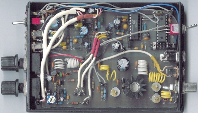
| Portable FM transmitter 1 W |
Introduction
This small FM transmitter includes a limiter, a microphone amplifier and a PLL digital tuning. All the parts are placed on one circuit board. The RF power is switchable between 1 W (HI) and 0,2 W (LO).

Technical specifications
Supply voltage: 12 V from accumulator or regulated power supply
Supply current (HI/LO): 270/170 mA
RF power HI: 1 W
RF power LO: 0,2 W
Impedance: 50-75 ohm
Frequency range: 87,5-108 MHz
Modulation type: wide-band FM
Modulation inputs: line, mic, RDS/MPX
PCB dimensions: 11,3 x 8,8 cm
Schematics:
The schematic diagram is divided into three parts: RF part (numbered from 1), PLL (numbered from 30) and audio part (numbered from 50).
Tuning
Connect a 6 V / 0,1 A bulb to the output and set the right frequency on PLL. Set the RF power to HI. Now turn on the transmitter. You should tune it on a receiver. Maybe you might stretch coils of the L1. Fix the L1 in position when the tuning voltage (on Q3) is in range 4-9 V. Then use C15, C16 and C17 to adjust the highest power (the highest light of the bulb). Then you can connect antenna and audio signal. Adjust R1 until the audio sounds as loud as the other stations.
The jumpers or DIP switches setting: pllfreq.txt.