|
It's not important if you use this RDS
encoder with one transistor FM bug or 1 kW transmitter. It will give your station all
common RDS features: Program service name, dynamic PS, Radiotext, Program Type
identification, Traffic Program, Traffic Announcement and Music/Speech flags, Alternative
Frequencies list and some more. This unit is ideal for mounting into a small transmitter.
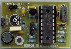
The design is based on the MRDS192 chip which processes and
stores the data and generates output signal. Analogue part is very simple due to fully
digital generated RDS signal.
Important
note: New improved version has been introduced - the MicroRDS.
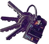
- Small dimensions
- Very low power consumption
- Operates stand-alone
- Unlimited reprogramming
- Wide control possibilities
- EEPROM memory for data storage during power-off
- Broadcast quality output signal
- Continuous RDS transmission during all operations
- 4 modes for dynamic/scrolling PS incl. word alignment
and one-by-one character scrolling
| RDS
services directly supported |
 PS (Program Service), PI (Program
Identification), PTY (Program Type), TP (Traffic
Program), TA (Traffic Announcement), DI (Decoder
Identification), M/S (Music/speech), AF (Alternative
Frequencies), RT (Radiotext), User Defined
Groups. PS (Program Service), PI (Program
Identification), PTY (Program Type), TP (Traffic
Program), TA (Traffic Announcement), DI (Decoder
Identification), M/S (Music/speech), AF (Alternative
Frequencies), RT (Radiotext), User Defined
Groups.
(The RDS services are described in Support)
 For more information download the MRDS192
datasheet. For more information download the MRDS192
datasheet.
| Dimensions: |
4.2 x 2.7 cm |
| Supply voltage: |
7-25 V |
| Supply current: |
9 mA |
| Output RDS signal voltage: |
adjustable 0-1.2 V p-p |
| RDS signal bandwidth: |
+/- 2.4 kHz (43 dBc) |
| Output impedance: |
<400 Ohm (DC-100 kHz) |
| Communication interface: |
synchronous, IIC based |
| |
|
Supply - Power supply connector
1: + 7-25 V
2: ground
Check the right polarity before connecting the power supply!!!
Out - RDS output
1: output
2: ground
LPT - PC port interface
1: SDA (serial data)
2: SCL (serial clock)
3: ground
Level - Output RDS signal level
adjust
| How to
connect the unit to a PC computer? |
For control purposes, the unit can be connected
either to LPT or COM port of the PC, each in unidirectional or bidirectional mode. The
control software supports all these connections.
In unidirectional mode you will not be able to read any data from the unit back to
the PC and you will not be able to detect if the data were sent successfully, but the
cable is easier to make. In standard situations any of the following diagrams will work.
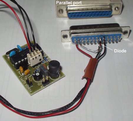
- MiniRDS to LPT port connection cable
(unidirectional):
The 680R resistor may be replaced by a diode as
in following case.
Direct connection between pins SDA and 6 is not recommended.
- MiniRDS to LPT port connection cable
(bidirectional):
- MiniRDS to COM port connection cable
(unidirectional):
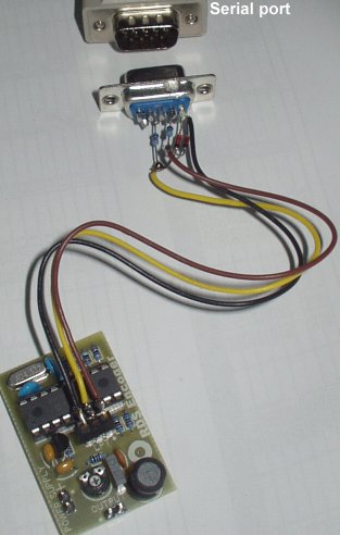
- MiniRDS to COM port connection cable
(bidirectional):
The R9 resistor on the board should be 2k or
less in this case (default value is 4k7).
Some important notes:
- The communication interface meets the IIC serial
synchronous bus standard with the clock rate limited to 600 Hz. So the unit can be also
controlled from almost any microcontroller.
- The PC control software emulates the IIC bus on a LPT
(parallel) or COM (serial) port.
- You must be logged under administrator laws in
Windows to access parallel port. Serial port can be accessed in all cases.
- Some low cost USB-to-COM adapters don't handle all
port pins required by the unit. You may use Port Access TEST built in the older control application to check it.
- In some cases bidirectional COM connection may not
work if non-standard port is used (USB adapter, laptop PC) - use any other connection.
- The RDS unit must be powered when sending any data.
- To store all permanent settings into EEPROM, click on
the Store button in the control software. If you forget to do this, your settings will be
lost when the power is disconnected.
- We do not supply any cables or adapters with this
unit.
As you can see, cable soldering and some basic
electronics knowledges are required. If you prefer complete plug-and-go solution rather,
look at the PIRA32.
| MiniRDS
control software for Windows |
Download: TinyRDS_Setup.exe
(730 kB) - supports all Windows version from 95 to 8
(Older version: Minirds.zip)
The software is very simple to use. After install
and first opening select appropriate hardware (MRDS192) and connection parameters on
Hardware card.
| How to
connect the unit to a transmitter? |
Answer to this question depends on the transmitter
you use:
Mono transmitter with audio or MPX input
connector (may used with stereo encoder plugged to this input)
Audio/MPX and RDS signal must be mixed together and pluged to the transmitter
input. There exist many ways to do this. You may use simple schematics provided below. The
resistor values are chosen approximately, but these values might be right.
Mono or stereo transmitter with RDS input
connector
It's the simplest situation. Connect the encoder to this input.
Stereo transmitter with audio left and audio
right connectors and no more inputs
An encroachment to the transmitter is necassary here. Find a varicap (capacitive
diode) in oscillator and connect the RDS input connector by the following diagram. Then
fix the connector in front panel of the transmitter.
|
