|
When experimenting with our own FM broadcasting, we sometimes need to use another FM station as a modulation source. For instance, we might want to extend that station's coverage — perhaps because people nearby struggle to pick it up on their mobile phones or cheap portable radios, whereas our setup, featuring a high-quality antenna and tuner, handles it with ease. Sure, the days when a desktop tuner was the standard for radio listening are long gone, as are many of the stations that were once worth rebroadcasting. Nevertheless, we will use this example as our starting point.
Generally, there are several ways to receive a signal from a selected FM station and re-transmit it on a different frequency (a process also known as retransmission or off-air relaying). For example, one could use a standard commercial FM tuner; however, such a device typically outputs only the left (L) and right (R) audio channels. These signals require pre-emphasis processing before being fed into a stereo encoder, the output of which is then sent to the transmitter. Wait a minute — we’ve "lost" the RDS data somewhere along the way, so it is usually necessary to include an RDS encoder as well. All in all, this isn't an ideal solution. A standard FM tuner breaks the complete multiplex (MPX) signal down into its individual components (L, R, RDS), which we then have to reassemble before transmission. A fundamentally simpler and technically "cleaner" solution is to extract the signal from the tuner immediately after FM demodulation — that is, in its original form, prior to the stereo decoder. Consequently, neither a stereo encoder nor an RDS encoder is required at the transmitter. However, a prerequisite is that the FM transmitter must be equipped with an MPX input—specifically, an input with a bandwidth of at least 60 kHz that applies no further processing to the signal (such as pre-emphasis or dynamic range compression). I mention this because some transmitters feature only Left and Right audio inputs with an integrated stereo encoder, making it generally impossible to feed an MPX signal into them. Conversely, transmitters lacking an internal stereo encoder can be used without issue.
Unfortunately, you will not find an MPX output on standard FM tuners. The only option is to create one via a minor modification, which is the focus of this article. The term "FM tuner" here refers to virtually any capable receiver. If the unit is an older model (dating from before the year 2000, for instance), the modification can almost always be performed. Newer receivers, however, may present a problem. The conventional notion that a receiver contains a discrete FM demodulator providing the necessary signal no longer holds true. More precisely, while an FM demodulator does exist—integrated as just one of dozens of structures within a single chip—it does not output this specific signal to any of the component's external pins. For instance, because demodulation is handled entirely in software, and outputting the MPX signal would require adding a relatively expensive D/A converter to the component. And why would a manufacturer do that? After all, an FM receiver designer doesn't need the MPX signal; they need the Left and Right audio signals—those are provided, and that’s the end of it. Don't like it? Well, neither do I :)
So, if we happen to own a conventionally designed FM tuner, we can output the MPX signal by following these few steps:
- Locate the FM demodulator integrated circuit on the board, identify its part number, and download its datasheet from the internet.
- Look up the pinout description in the datasheet and search for a label such as FM OUT, Demodulator OUT, Detector OUT, MPX OUT, or something similar.
- Mark the corresponding pin directly on the FM tuner board. For completeness, we should also positively identify the ground pin (GND).
- Locate a suitable supply voltage on the board (typically in the 8 to 12 V range), e.g.,
the output of a voltage regulator.
- Modify the FM tuner using the circuit shown below, including a suitable connector
mounted on the tuner's rear panel (preferably an RCA/Cinch or BNC connector).
- Feed a test FM signal with a standard 75 kHz deviation from an RF generator into the tuner
and use an oscilloscope to measure the actual peak-to-peak voltage at the MPX output (this step
is optional but can be useful).
Although there is (or rather, was) a wide variety of integrated circuits for FM receivers,
the signal parameters at the relevant FM demodulator pin are similar. This is partly
to allow different components to be combined within the tuner circuitry. The pin in question
usually provides an MPX signal with a peak-to-peak amplitude of 1 V and an output
impedance ranging from a few to several tens of kilohms. To utilize this signal
without interfering with the tuner's standard functions, we must amplify it
and, if necessary, provide DC isolation.
The simplest circuit configuration (Fig. 1) uses an operational amplifier
connected as a voltage follower. This configuration does not amplify voltage but significantly reduces
output impedance without loading the signal source (the input impedance of such
an amplifier can reach several tens of megaohms). For some applications, an MPX signal
swing (level) of 1 Vpp is more than sufficient. The amplifier connects directly to the
demodulator outputs, thereby inheriting its DC component, which is subsequently
filtered out by the output capacitor.
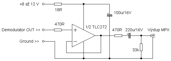
Fig. 1 - Simple MPX signal amplifier with unity voltage gain.
If a larger signal swing is required, the configuration shown in Fig. 2 is used. Here,
the necessary DC bias for the amplifier (half the supply voltage) is generated
using a resistive divider to prevent signal clipping at higher gain levels.
Replacing resistor R2 with a trimmer potentiometer allows for continuous
adjustment of the output level within a certain range.
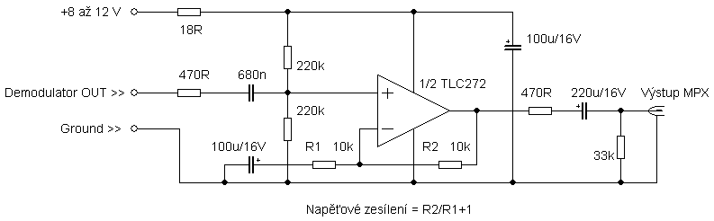
Fig. 2 - MPX signal amplifier with higher voltage gain.
The amplifier should be connected using a shielded cable. A printed circuit board
is likely unnecessary; components can simply be soldered directly onto the output
connector or onto a small piece of prototyping board. Component values are not critical;
treat the listed values as a guide — in practice, the circuit will work with whatever
you happen to have on hand. The operational amplifier used should have a
slew rate of at least a few V/µs and high-impedance inputs (FET, CMOS).
If the package contains multiple op-amps, the outputs and inverting inputs (-)
of any unused op-amps should be connected together.
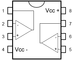
Fig. 3 – Most common op-amp circuit configuration.
So, our tuner is now equipped with an MPX output. What can we do with it? Besides
re-broadcasting the selected FM station in its original form, we can use the MPX
output for detailed analysis or as an ideal signal source for an external
RDS decoder (units known as RDS Manager, Wetekom, Raydees, as well as various
circuits based on the TDA7330 chip, etc.). It is even better if we can feed the
entire MPX signal into a computer — provided our sound card supports recording
at a sample rate of 192 kHz. This makes it possible, among other things, to decode
RDS entirely via software; see http://rdsspy.com.
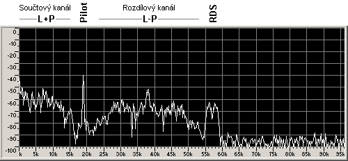
Fig. 4 – MPX signal spectrum in the GoldWave program. Recorded using a
sound card supporting a 192 kHz sampling rate.
Note! You proceed at your own risk. The author does not perform the
described modifications and accepts no liability for any damage to the tuner.
Many older tuners were — and remain — technical marvels, so please be careful ;)
Author: Ing. Jan Kolar
|