COM port to Mini RDS Encoder connection.
Data cable connection between PC and the Mini RDS Encoder.
| Meaning | PC | RDS Encoder | ||
| LPT | COM (9pin) |
COM (25pin) |
||
| Data | 6 | 4* | 20* | 1 (marked) |
| Clock | 5 | 7* | 4* | 2 |
| Ground | 25 | 5 | 7 | 3 |
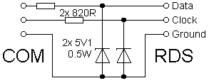
* Important! The LPT parallel port pins can be connected directly to the Mini RDS encoder, for COM port connection use this schematic diagram and add two 820R resistors in series and two 5V1 Zener diodes connected to Ground:
COM port to Mini RDS Encoder connection.