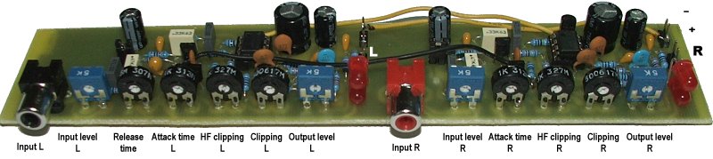
| Compressor/limiter/clipper - stereo version |
Stereo version of the limiter includes common gain control for both channels. It does not affect the stereo information. Release time trimmer is common for both channels.
Characteristics:
| Supply voltage: | 9-16 V |
| Quiescent supply current (12 V): | 30 mA |
| Output voltage: | linear adjustable 0-3.5 V p-p (0-1.2 V rms) |
| Lower cut-off frequency (3 dB): | input: 25 Hz, output: <2 Hz |
| Upper cut-off frequency (3 dB): | 14.5 kHz |
| Min. input voltage: | 0.6 V p-p (0.2 V rms) |
| Input impedance: | 5000 ohm |
| Output impedance: | 500 ohm |
| Signal-to-noise ratio: | >70 dB |
Schematic diagram:
Part list:
Left channel:
R1, R3 - 10k
R2 - 1k
R4, R5 - 1M
R6 - 18k
R7, R8, R15-R17, R19 - 33k
R9 - 1M5
R10, R12, R14, R18 - 470R
R11 - 270R
R20, R23, R25 - trimmer 5k
R21 - trimmer 5M
R22 - trimmer 1k
R24 - trimmer 500R
C1 - 4n7 (EU) or 6n8 (USA), plastic
C2 - 470n plastic
C3, C6 - 4n7 plastic
C4 - 330n plastic
C5, C7, C8, C12 - 10n ceramic
C9 - 330p ceramic
C10 - 470p ceramic
C11 - 82p ceramic
C13 - 10u/25V tantalum
C14 - 470u/25V electrolytic
C15, C16 - 220u/10V electrolytic
U1 - TLC272
Q1 - BC557B
Q2 - BF245C
D1, D2 - Red!!! LED diode 5 mm,
medium luminance (eg. 200 mcd)
J2 - jumper
Right channel:
R1, R3 - 10k
R2 - 1k
R4, R5 - 1M
R6 - 18k
R8, R15-R17, R19 - 33k
R9 - 1M5
R10, R12, R14, R18 - 470R
R11 - 270R
R20, R23, R25 - trimmer 5k
R22 - trimmer 1k
R24 - trimmer 500R
C1 - 4n7 (EU) or 6n8 (USA), plastic
C2 - 470n plastic
C3, C6 - 4n7 plastic
C4 - 330n plastic
C7, C8, C12 - 10n ceramic
C9 - 330p ceramic
C10 - 470p ceramic
C11 - 82p ceramic
C14 - 470u/25V electrolytic
C15, C16 - 220u/10V electrolytic
U1 - TLC272
U2 - 78L05
Q1 - BC557B
Q2 - BF245C
D1, D2 - Red!!! LED diode 5 mm,
medium luminance (eg. 200 mcd)
J2 - jumper
Tips:
Following steps are recommended for the stereo version:

PCB:
Top side. Includes 3 wire-bridges.
Bottom side.
(C) 2007 Pira CZ. Commercial use is forbidden.