 Why it is important to use a limiter?
| Limiter |
Important! New version of this circuit exists. Click here!
Why it is important to use a limiter?
Audio signals as music or speech have big dynamic ranges. There are silent and loud sections. These audio signals aren't too good for a transmitter, which requires audio signal with constant level on the input. Limiter is a device, which weakens loud signals and intensifies silent signals. On its output there is signal with constant level.
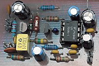
Following circuit is the simplest limiter possible. It nicely shows how the limiter works. Good circuit for unassuming use.
Technical specifications
Supply voltage: 10-14 V stab.
Supply currents: 20 mA
Audio input: impedance 20 kOhm, optional preemphasis
Output voltage: 0,4 V rms
Dynamic range: >50 dB
Output voltage vs. input voltage (with C8 placed)
Schematic diagram
Parts list
Resistors:
R1 - 68 k
R2 - 22 k
R3 - 180 k
R4 - 10 M
R5 - 10 k
R6 - 47 R
R7 - 240 k
R8 - 1,5 k
R9 - 820 R
Capacitors:
C1 - 100 p (ceramic)
C2 - 1 n (plastic)
C3, C6, C12 - 100 n (ceramic)
C4, C11, C13 - 100 u (electrolytic)
C5 - 0,33 u (tantalum)
C7, C8 - 10 u (electrolytic)
C9 - 220 n (plastic)
C10 - 47 n (ceramic)
C14 - 470 n (plastic)
Misc.:
T1 - BF245C
T2 - BC556B, BC307
IC1 - LM386
Don't place the C8 if you don't want to use whole dynamic range. Then you will get much
better S/N ratio.
You may adjust release time by C7 and R4 values.
PCB layout