| Pira.cz Stereo Encoder for FM broadcasting |
This stereo encoder is a halfway between analogue and digital processing. It combines the best from both domains to provide high-quality and easy to build device. The sampling frequency used in this stereo encoder is 97 times (!!!) higher than the pilot tone frequency. This makes very easy to reject all spectral residues around the sampling frequency without affecting the main signal characteristics. Using of a microcontroller allows to build this stereo encoder with reduced part count and get excellent results in real operation.
| Important
note: Commercial production of a device based on this design or its substantial
part (incl. the internal software) is subject to the license terms placed in the
file stereo.zip. Anybody who is selling this device on a commercial basis is obliged to indicate the "Pira.cz" origin in
the product name or description and use all components with original values and in original quality. Disclaimer: This device has never been produced by us for the purpose of sale. We take no responsibility for any 3rd party products! Whenever possible, we recommend to build this device yourself. If you decide to buy this device anyway, please keep on mind: 1) always check the seller's rating and history, 2) never buy the item if the "Pira.cz" origin is not mentioned in the product name or description. |
This stereo encoder advisedly does not contain any preemphasis circuit. Remember the key fact: a compressor/limiter/clipper device must be always present between the preemphasis circuit and the stereo encoder or modulator. Only this configuration ensures loud sound without exceeding the maximum frequency deviation limit (75 kHz). The stereo encoder is designed to provide really good sound. This always needs to use the compressor/limiter/clipper device where the preemphasis is precisely assured. The Pira.cz Compressor/Limiter/Clipper is highly suitable for this task.
Basic block diagram:
Characteristics:
| Supply voltage: | 9-16 V (stabilized) |
| Quiescent supply current (12 V): | 34 mA |
| Audio 19 kHz rejection: | 40 dB |
| Channel separation at 1 kHz: | >55 dB |
| Subcarrier rejection: | >60 dB |
| Pilot sampling frequency: | 1.843 MHz (19 kHz x 97) |
| Subcarrier sampling frequency: | 1.843 MHz (38 kHz x 48.5) |
| Pilot sync. output: | TTL |
| Max. audio input voltage: | 5 V pp (1.75 V rms) |
| Pilot tone level: | linear adjustable 0-0.5 V pp |
| Output voltage gain: | linear adjustable 0-1.5 |
| Audio input impedance: | 2000 ohm |
| RDS input impedance: | 1000 ohm |
| MPX output impedance: | 500 ohm |
| Pilot sync. output impedance: | 10000 ohm |
| Signal-to-noise ratio: | >70 dB |
Schematic diagram:
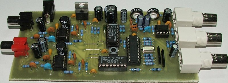
Part list:
U1-U3 - TLC272, TS272
U4, U5 - 74HC4053 (74HCT4053)
U6 - 7805
U7 - PIC18F1220-I/P with stereo.hex file inside
Y1 - Crystal 7.3728 MHz (7.372 MHz)
SW1 - Button
L1, L2 - Coil 15 mH 5% (09P-153J), 80 ohms or less
RN1, RN2 - SIL resistor network 3x 1k (discrete, 6 pin)
C1, C2 - 47p (ceramic)
C3, C4, C5, C9, C24, C33-C35 C37 - 100n (ceramic)
C6 - 82p (ceramic)
C7, C19, C20, C30, C31 - 270p (ceramic)
C8, C11, C14, C22, C23 - 220u/10V (eletrolytic)
C10, C21, C25, C32 - 560p (ceramic)
C12, C36, C38, C39 - 100u/10V (eletrolytic)
C13 - 470u/25V (eletrolytic)
C15, C26, C40 - 22p (ceramic)
C16, C27 - 2n7 (foil)
C17, C28 - 4n7 (foil, 5%)
C18, C29 - 10n (ceramic)
R1, R24 - 20k (1%)
R2-R9, R30, R31, R38, R39, R49, R50 - 2k (1%)
R10 - 160k
R11 - 330k
R12, R16, R27-R29, R40-R42 - 39k
R13 - 82k
R14, R17, R18, R20, R21, R25, R32, R43 - 10k (1%)
R15, R26 - 1k
R19 - 470R
R33, R34, R44, R45 - 30k (1%)
R35, R46 - 16k (1%)
R36, R47 - 47R
R37, R48 - 680R
R22, R23 - Trimmer 5k
HEX file: stereo.zip
(WDT: on, Osc.: HS PLL, MCLRE: RA5), version 2.0.
Suitable free PIC programmer is for example here: http://www.members.aon.at/electronics/pic/picpgm/.
We do not provide the PIC programming, PCB nor complete kit sale for this
device.
Adjusting elements description:

Pilot level adjustment: The pilot level should be set to 9 % of the total deviation (75 kHz), measured in peak-to-peak values. For example, if audio input level is 2 V pp, set the pilot tone level to 0.2 V pp (the adjustment is linear with the max. of about 0.5 V pp).
Output level (gain) adjustment tip: If possible, it's recommended to set high output level and adjust lower sensitivity on the transmitter/exciter rather than set low output level and adjust high sensitivity. This way gives getter S/N ratio. Is it clear?
Note: The output level adjustment has no effect on pilot-to-audio ratio.
Mode selection: Click and hold the button until the mode change is indicated by acoustic signal (number of beeps indicates the mode set). The device will remember the setting. Mode table:
| Mode | L-P | Pilot |
| 1 | +0 dB | 0 deg. |
| 2 | mono | |
| 3 | +0.05 dB | 0 deg. |
| 4 | +0 dB | -4 deg. |
| 5 | +0 dB | +4 deg. |
Mode 1 is the default and recommended. Mode 2 switches to monaural operation. Modes 3 to 5 can compensate transient characteristics in some cases and improve channel separation, but have no reason for nonspecialists.
PCB:
Bottom side.
Top side.
Connection to the RDS encoder:
Connection to PIRA32 RDS Encoder.

Connection to MiniRDS Encoder.
Output signal characteristics measured:
Output spectrum - R: 1 kHz, L: 1 kHz.
Output waveforms (incl. pilot) - R: 1 kHz, L: no
signal.
Output spectrum - R: 1 kHz, L: no signal.
Output spectrum - Real music signal.
Output spectrum - Real music signal.
Channel separation test: TA7343 based stereo decoder was used for this test, connected directly to the stereo encoder output. Channel separation of more than 50 dB was reached, in accordance with the TA7343 datasheet - it's the maximum separation value possible with the TA7343. It's possible to say that the real channel separation of the stereo encoder is more than 6 dB higher.
BH1415F output spectrum comparison:
These two pictures show MPX spectrum of the BH1415F circuit for comparison. Typical channel separation never exceeds 40 dB. The circuit has also expressive overmodulation problems and makes very hard to connect any RDS encoder. Are you still interested?
R: 1 kHz, L: 1 kHz.
Real music signal.
(C) 2009 Pira.cz. Commercial use is subject to the license terms.